Neurobus 2.0
Neural interfaces are widely used in the study of complex interactions between neurons within the brain. To understand the activity of neural cells, nervous tissue is first stimulated with a current or voltage signal and afterwards its electrical activity is observed. This response is usually in the range from 50μV up to 1mV, which is much lower than the stimulation signal that can easily exceed a voltage range of several Volt. The big difference in these amplitude levels make the design of the analog front-end challenging, as low noise and low power recording circuits must be combined with a high voltage stimulator.
Another big challenge in the design of neuromodulators is the demand for higher spatial resolution, which requires not only one, but as many as possible recording and stimulation channels. A higher spatial resolution allows on the one hand side a more detailed look into the brain’s functionality, on the other hand side neurons can be triggered more accurate enabling more effective treatments. But increasing the channel count directly increases not only the area but also the power consumption of the system, which are both strictly limited by the requirements for an implantable system.
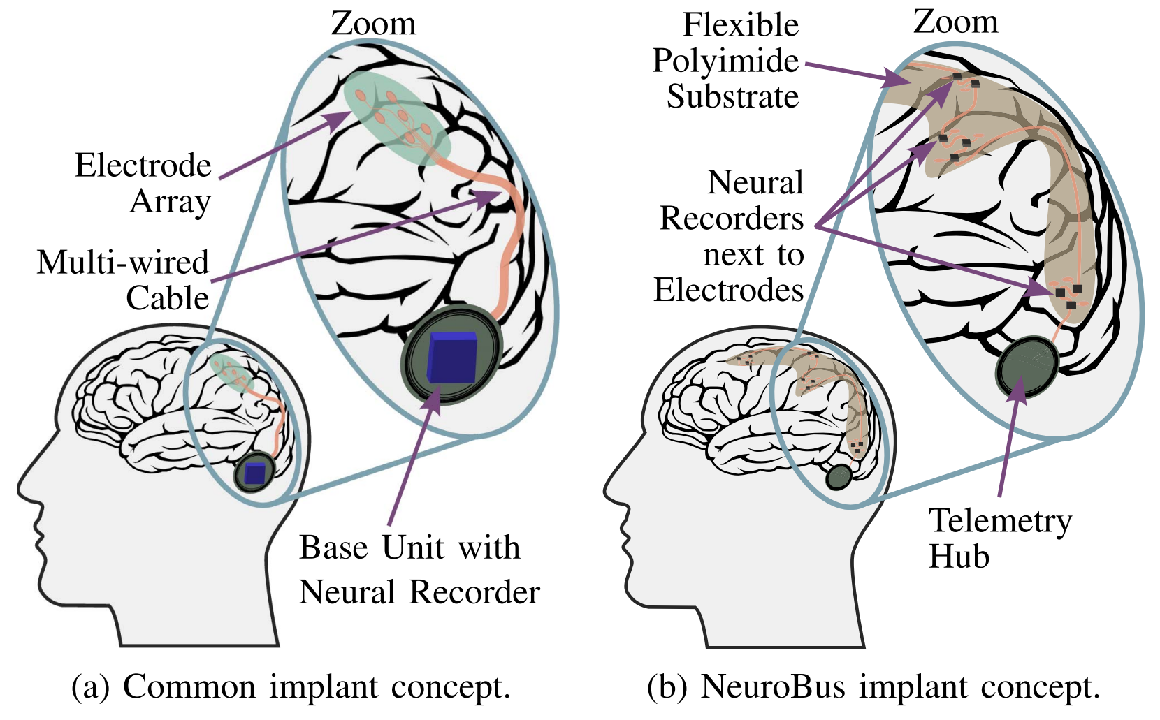
Typically, the recording and stimulation circuits of all channels are implemented on a single ASIC. This centralized approach however requires a large silicon area to accommodate the demand on a high channel count to achieve high spatial resolution. The encapsulated ASIC is typically placed in the cranial bone or the chest due to less strict area constraints in these regions of the body. Recording and stimulation electrodes must be connected to the implant with long multi-wire cables. The centralized concept suffers from increased cabling effort and degraded signal integrity due to the large distance between the neurorecorder and the recording electrode.


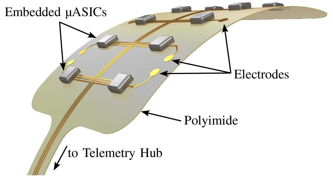
Neurobus aims to solve these issues at the core. Instead of one central unit, the recording and stimulation circuits are distributed on a large number of small implants, so called μASICs. This approach enables the recording and stimulation units close to their corresponding electrodes, reducing the wiring effort and improving the signal integrity. Due to their small size, μASICs can be directly placed on the brain tissue. All units are interconnected with a data bus. A central unit, which can be placed away from the brain tissue, is responsible for power management and communication with an external unit.
In the first iteration of the project, the fundamentals of materials science and microelectronics were established. A first neurorecorder prototype μASIC was developed and tested. The second iteration aims to optimize the performance, power, and area consumption through a novel architecture. Moreover, the system will be expanded with a stimulator to enable true closed-loop neuromodulation.
Publications
2. M. Sporer et al., "NeuroBus - Architecture for an Ultra-Flexible Neural Interface," in IEEE Transactions on Biomedical Circuits and Systems, vol. 18, no. 2, pp. 247-262, April 2024
DOI: 10.1109/TBCAS.2024.3354785
1. M. Sporer et al., "NeuroBus – Architecture and Communication Bus for an Ultra-Flexible Neural Interface," 2023 IEEE International Symposium on Circuits and Systems (ISCAS), Monterey, CA, USA, 2023, pp. 1-5
DOI: 10.1109/ISCAS46773.2023.10181816
DFG Projekt „NeuroBus 2.0“ - OR245/15-2
